Quick Start – Arduino
Software Preparation
The Arduino library is written in C++ and communicates with the AI Vision Sensor via I²C. Based on this library, programs can be developed with higher efficiency and richer functionality.
Note: The examples in this library are mainly based on the
WireI²C library, but this library does not depend on Wire. You can refer to theoverrideexamples to use this library in any environment.
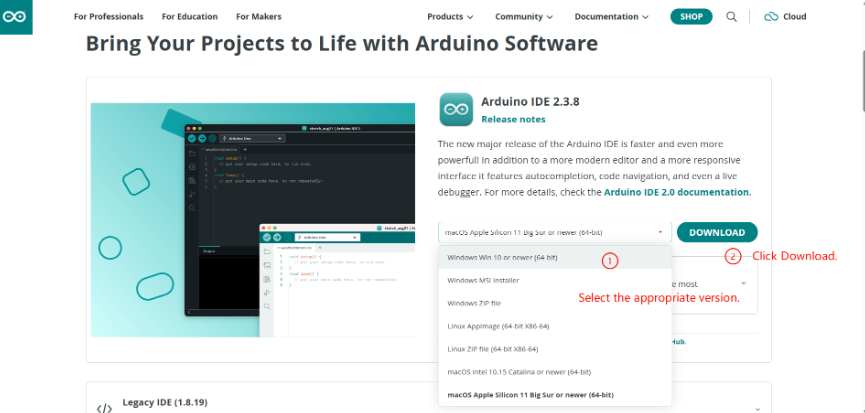
Obtain the Software
Open the Arduino IDE, obtain the version suitable for your computer system, and download and install it.
Obtain the Library
This document provides the Vision Module API library for download from GitHub and Gitee.
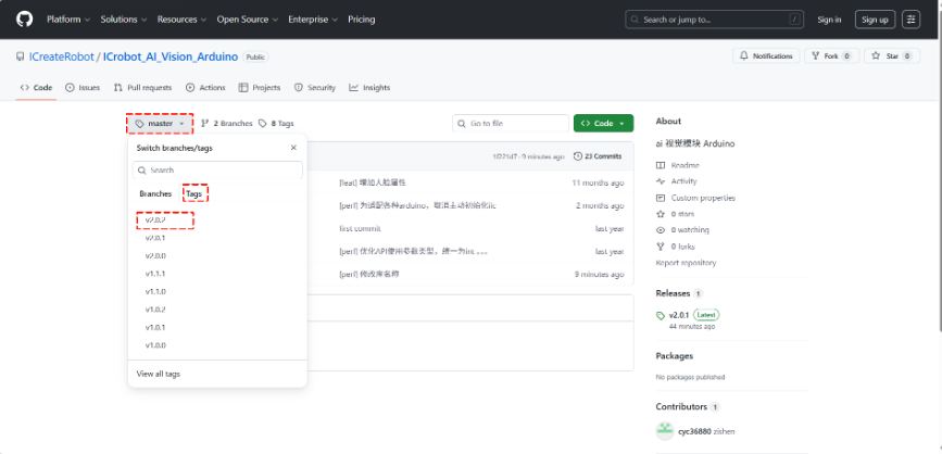
Obtain from GitHub
Step 1: Go to GitHub.
Step 2: Click the master branch, then select the latest version from the Tags on the right.
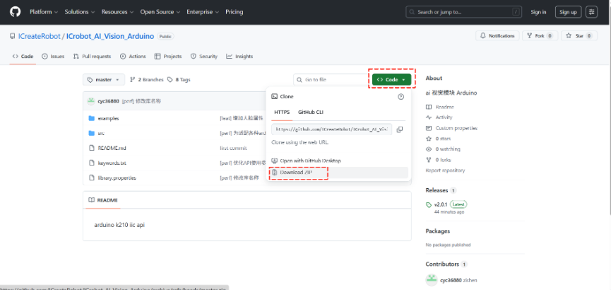
Step 3: Click Code and select Download ZIP to download the library package.
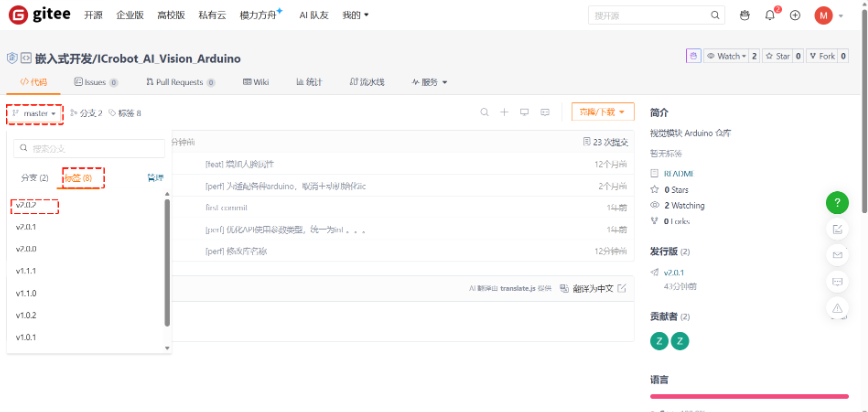
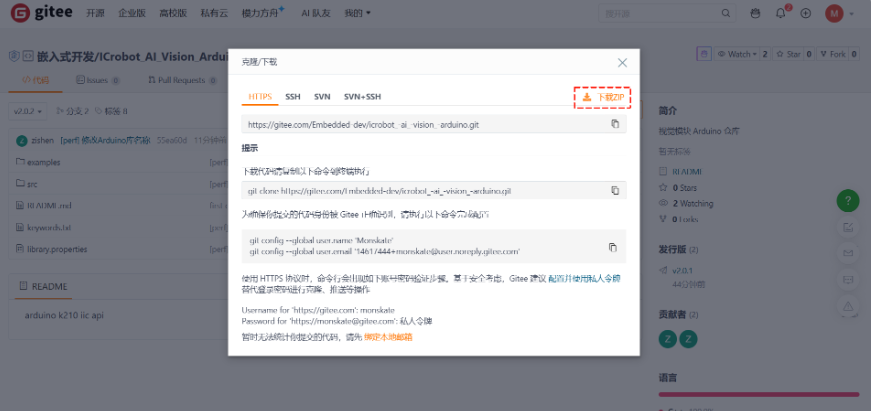
Obtain from Gitee
Step 1: Go to Gitee.
Step 2: Click the master branch, then select the latest version from the标签on the right.
Step 3: Click克隆/下载and select下载ZIPto download the library package.
Import the Library
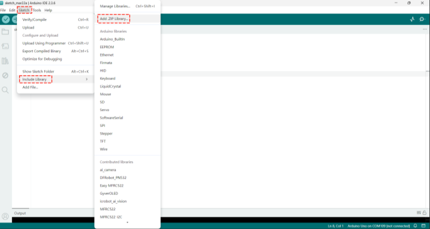
Step 1: Open the programming software, create a new project, findInclude Libraryin theSketch, and clickAdd .ZIP Library.
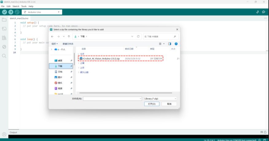
Step 2: Select the downloaded library and click Open in the bottom-right corner.
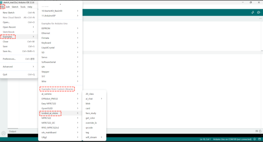
Step 3: In the File tab, open Examples. In the Examples tab, find the Examples from Custom Libraries. If you find icrobot_ai_vision, the library has been successfully imported.
Hardware Preparation
Device Contents
|
|
|---|---|
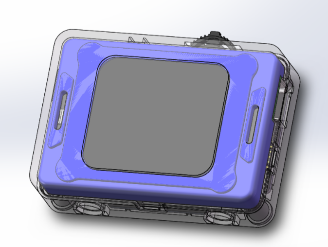
ICreateRobot AI Vision Sensor |
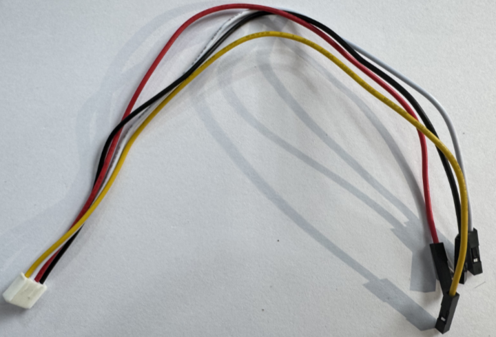
Grove to 4-pin Dupont cable |
|
|
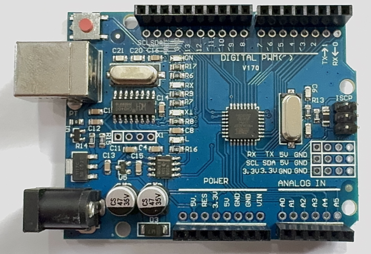
Arduino Uno |
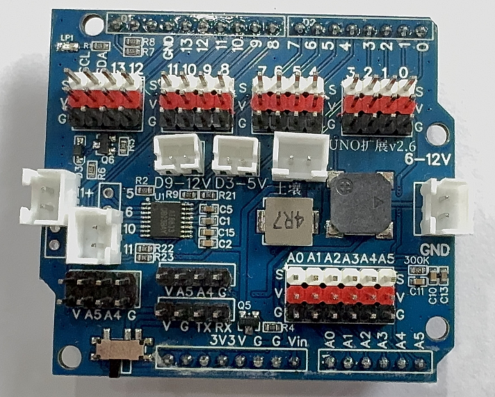
Expansion Shield |
|
|
USB Connection Cable |
Device Operation
The AI Vision Sensor is connected to the Arduino Uno development board via a Grove-to-4-pin Dupont cable. The specific operation steps are as follows:
|
|
|---|---|
1. Insert the expansion board into the Arduino Uno development board. |
2. Connect the other end of the adapter cable to the AI Vision Sensor, and power the Arduino Uno development board via the cable from the computer. |
|
|
3. After the module powers on, rotate the dial to go to Settings and change the port protocol to I²C. |
For connecting the Grove port to Arduino board pins, please refer to the Grove port pin description.
Usage Examples
The icrobot_ai_vision library provides multiple example programs, each containing detailed comments. Combined with the Arduino user guide, these examples allow quick mastery of the library. Below, three examples are used to illustrate how to use and compile the routines
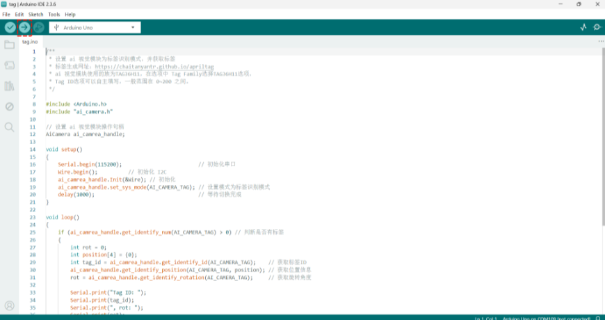
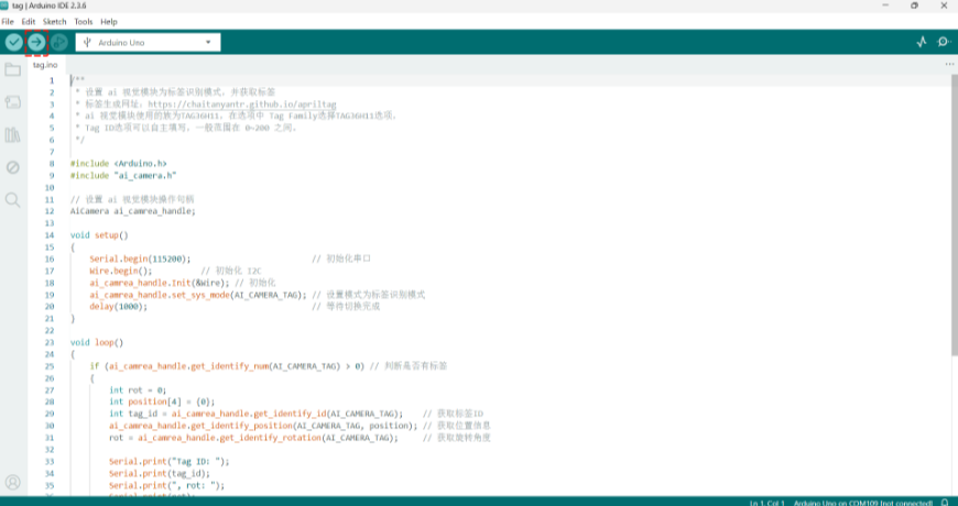
Example 1: Vision Mode – Label Recognition
Example Content:
Connect the AI Vision Sensor to the Arduino UNO development board and switch to Label Recognition in Vision Mode. If the vision module does not detect a label, the board prints “No tag” to the serial monitor; otherwise, it prints the label ID, rotation angle, and label coordinates.
Operation Steps:
|
|
|---|---|
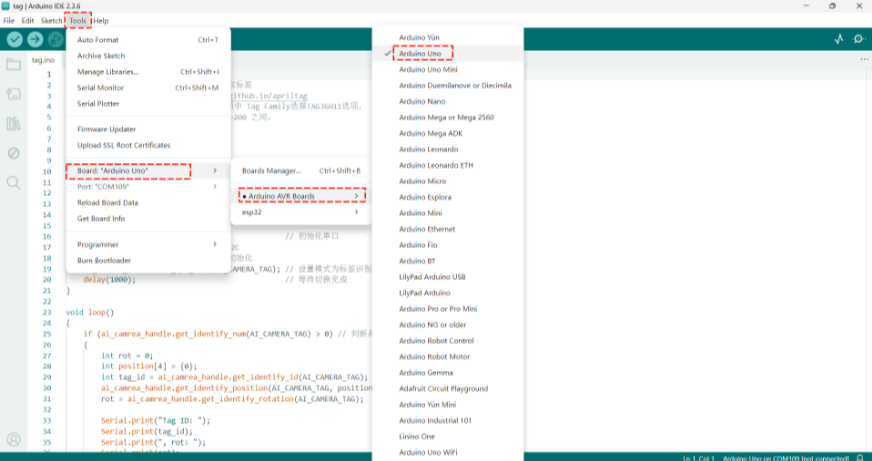
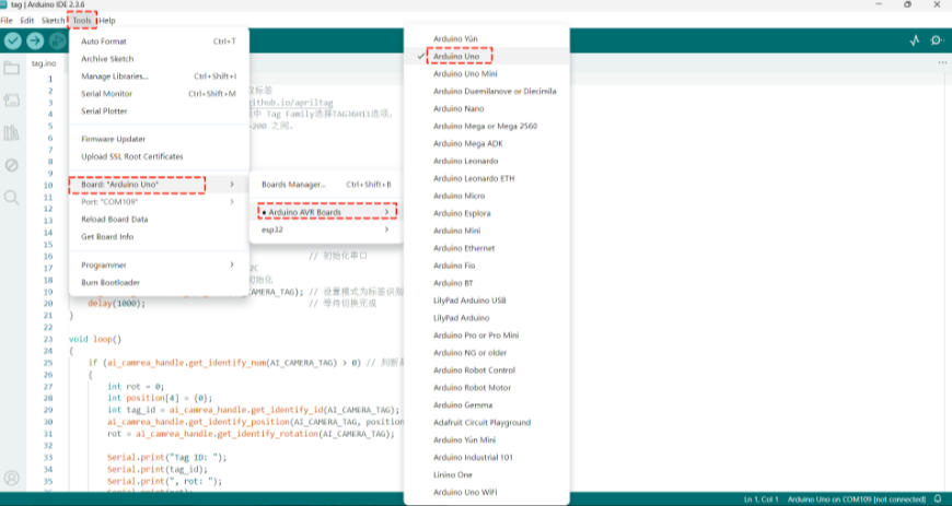
1. Select the |
2. Insert the expansion board into the Arduino Uno development board. |
|
|
3. Connect the other end of the adapter cable to the AI Vision Sensor, and power the Arduino Uno development board via the cable from the computer. Select Vision Mode. |
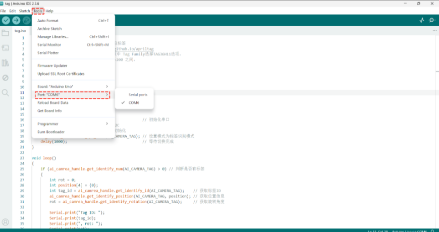
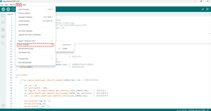
4. In the |
|
|
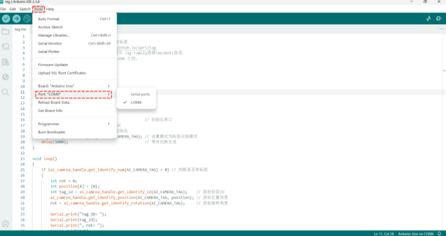
5. In the |
6. Compile and download the program. |
|
|
7. Prepare the labels. |
8. Execution Result: The serial monitor prints the label ID, rotation angle, and label coordinates. |


Example 2: Conversation Mode – Voice-Controlled Movement
Example Content:
Connect the AI Vision Sensor to the Arduino UNO development board and switch to Conversation Mode. The serial monitor prints the user’s voice input for movement commands and speed information.
Operation Steps:
|
|
|---|---|
1. Select the |
2. Insert the expansion board into the Arduino Uno development board. Connect the yellow wire of the Grove-to-4-pin Dupont cable to the SCL pin on the expansion board, |
|
|
3. Connect the other end of the adapter cable to the AI Vision Sensor, and power the Arduino Uno development board via the cable from the computer. Select Conversation Mode. |
4. In the |
|
|
5. In the |
6. Compile and download the program. |
|
|
7. Execution Result: The serial monitor prints the voice input commands and speed. |


Example 3: WiFi Image Transmission – Web Joystick
Example Content:
Connect the AI Vision Sensor to the Arduino UNO development board and switch to WiFi Image Transmission. The webpage displays the camera feed, and the serial monitor prints the joystick values.
Operation Steps:
|
|
|---|---|
1. Select the |
2. Insert the expansion board into the Arduino Uno development board. Connect the yellow wire of the Grove-to-4-pin Dupont cable to the SCL pin on the expansion board, |
|
|
3. Connect the other end of the adapter cable to the AI Vision Sensor, and power the Arduino Uno development board via the cable from the computer. Select WiFi Image Transmission. |
4. In the |
|
|
5. In the |
6. Compile and download the program. |
|
|
7. Execution Result: The serial monitor prints the joystick values. |