User Guide - make:code
Vision Mode
Coding Programming
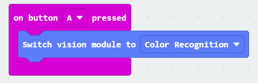
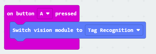
The K210 AI Vision Module starts up when the micro:bit is powered on and enters the default color recognition mode after booting. When programming, it is recommended not to switch the module’s mode immediately after powering on, as the module requires about 5 seconds for initialization.
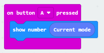
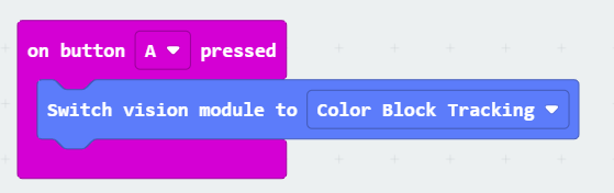
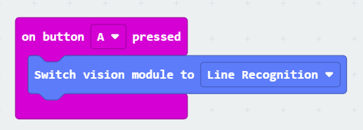
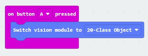
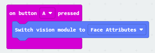
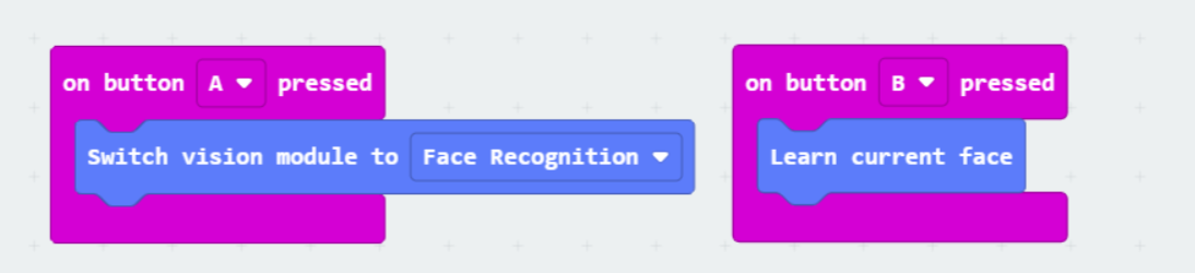
Instead, it is recommended to use triggers such as buttons (as shown in the diagram below) to switch the module’s AI recognition mode after the initialization period.
The “Current Mode” programming block can return a number (0~9) to represent the AI model currently running on the K210 AI Vision Module.
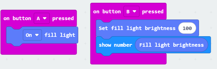
You can programmatically control the module’s built-in fill light, with the brightness range from 0 to 100, and also read the current fill light brightness.
Color Recognition
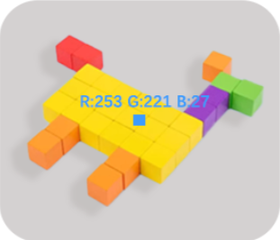
A rectangular area is displayed at the center of the screen, and the module will calculate the RGB average value of the pixels within this area.
The color displayed on the screen represents the average RGB value of that area, making it easier for standardized recognition.
The color recognition programming block can read the average color value within the recognition box, providing feedback in RGB format. The RGB values range from 0 to 255.
Color Block Tracking
Press the button to enter the color selection mode.
Rotate the button left or right to select the tracking object from six built-in colors (Red, Green, Blue, Yellow, Black, White).
If the last option is selected, align the rectangular frame at the center of the screen with the target color and press the button again to lock the current color as the tracking target.
Color Block Tracking Mode will search for the largest specified color area in the line of sight and return the location information of the color block.
X: Represents the X-coordinate of the tracked color block.
Y: Represents the Y-coordinate of the tracked color block.
W: Represents the width of the tracked color block.
H: Represents the height of the tracked color block.
Apriltag Recognition
Supports recognition of two formats of AprilTag codes: TAG36H11 and TAG16H5.
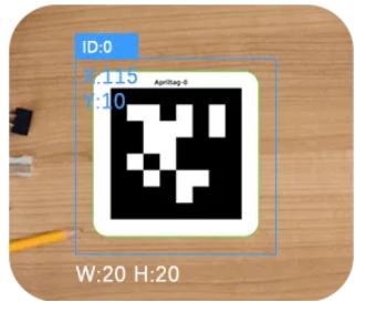
Point the camera at the tag, and the screen will automatically frame and display the corresponding X, Y, W, H, and the tag’s code value.
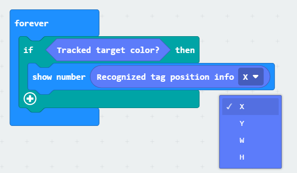
Tag Recognition Mode will search for all detectable AprilTag codes in the line of sight and display the location information of the tag along with the number represented by the AprilTag code.
X: Represents the X-coordinate of the tracked tag.
Y: Represents the Y-coordinate of the tracked tag.
W: Represents the width of the tracked tag.
H: Represents the height of the tracked tag.
Line Recognition
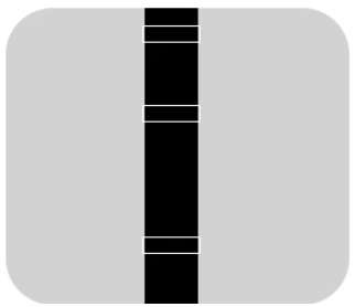
Used to recognize black lines on a white background.
The screen will identify and frame the line contours in the upper, middle, and lower regions of the screen based on the content.
Recommended environment: No other interference in the frame.
Line Recognition Mode will search for detected black lines in the line of sight and fit them into the corresponding upper, middle, and lower selection boxes, displaying the line’s location information.
X: Represents the X-coordinate of the tracked line.
Y: Represents the Y-coordinate of the tracked line.
W: Represents the width of the tracked line.
H: Represents the height of the tracked line.
20-Class Object Recognition
The module can recognize the following 20 common objects:
“Airplane”, “Bicycle”, “Bird”, “Boat”, “Bottle”, “Bus”, “Car”, “Cat”, “Chair”, “Cow”, “Dining Table”, “Dog”, “House”, “Motorcycle”, “Person”, “Potted Plant”, “Sheep”, “Sofa”, “Train”, “Television”.
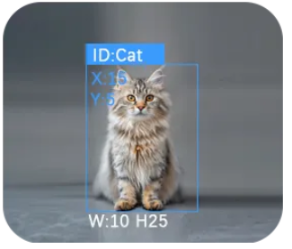
Point the module at the object you want to recognize. The recognition results will be framed on the screen, and the object name will be displayed.
The module supports recognizing up to 4 objects simultaneously.
20-Class Object Recognition Mode will search for AI model-recognizable objects in the line of sight, identifying and framing up to 4 objects at a time. The recognition results will display the object type and location information.
X: Represents the X-coordinate of the recognized object.
Y: Represents the Y-coordinate of the recognized object.
W: Represents the width of the recognized object.
H: Represents the height of the recognized object.
QR Code Recognition
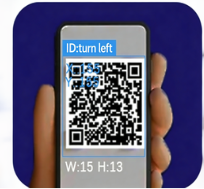
Supports recognition of standard square QR codes composed of black and white blocks. Only one QR code can be recognized at a time.
After pointing the camera at the QR code, the screen will frame the QR code and display the decoded content, along with the QR code’s X, Y, W, and H.
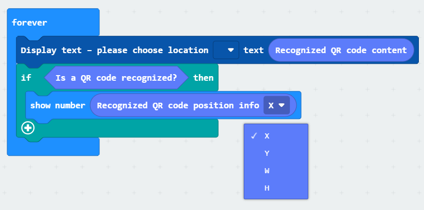
QR Code Recognition Mode will search for all detectable QR codes in the line of sight and display the QR code’s location information and decoded message.
X: Represents the X-coordinate of the tracked QR code.
Y: Represents the Y-coordinate of the tracked QR code.
W: Represents the width of the tracked QR code.
H: Represents the height of the tracked QR code.
Face Attribute Recognition
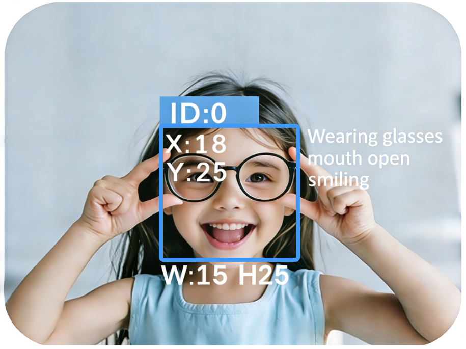
Point the camera at a face, and it will recognize three attributes: whether the mouth is open, whether the person is smiling, and whether they are wearing glasses.
Up to 4 faces can be recognized at a time, with each face displaying the corresponding attribute results.
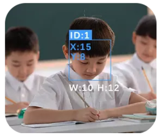
Face Attribute Recognition Mode will detect faces in the line of sight and display the detection location, face ID, and face attribute information.
X: Represents the X-coordinate of the detected face.
Y: Represents the Y-coordinate of the detected face.
W: Represents the width of the detected face.
H: Represents the height of the detected face.
Face ID Recognition
When a face is recognized for the first time and has not been learned, it will be highlighted with a white bounding box.
After framing the face, press the button to start learning and assign an ID (0–3). The module supports saving the learned data even after power-off.
Up to 4 faces can be learned.
Long-press the button to bring up a confirmation dialog to clear the learned face data. After confirmation, all learned records will be erased.
The learned face data is retained after power-off. If not cleared, the previously learned faces will be loaded upon the next power-up.
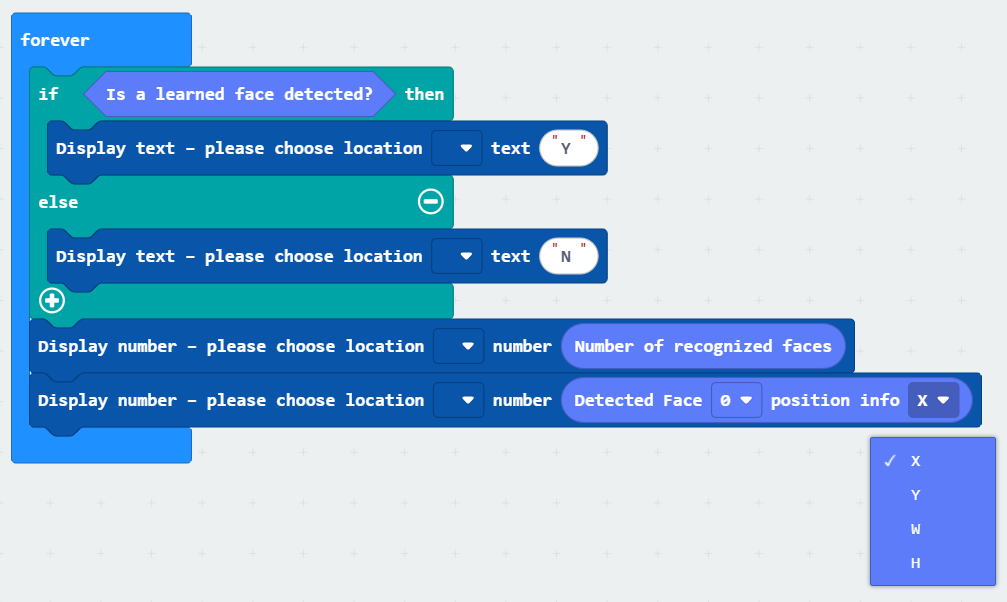
Face Recognition Mode will detect faces in the line of sight and display the recognized location, face ID, and face attribute information.
X: Represents the X-coordinate of the recognized face.
Y: Represents the Y-coordinate of the recognized face.
W: Represents the width of the recognized face.
H: Represents the height of the recognized face.
Deep Learning
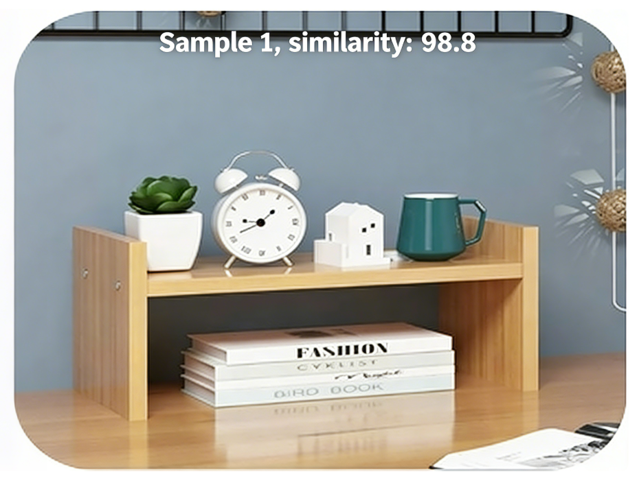
Supports learning up to 2 types of targets, with 2 images required for each type.
Press the button to start learning the current category. The current category number will be displayed in the top-left corner, and the number of images taken will be shown in the top-right corner.
If no further button presses are made within 5 seconds after learning category 0, the system will automatically switch to recognition mode.
After reaching the maximum number of categories for learning, either a 5-second wait or a button press will switch to recognition mode.
Once in recognition mode, the function mode cannot be switched. A prompt will appear asking to reset learning first. To reset, long-press the button and select Confirm in the popup to reset the learning data.
Deep learning data is not retained after power-off. The learning process will need to be repeated on the next power-up.

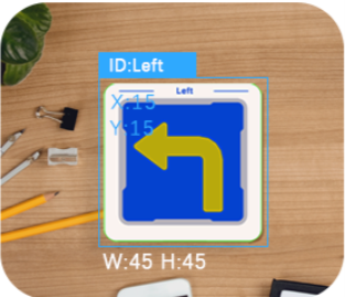
Card Road Sign Recognition
Supports recognition of the following 6 traffic icons:
Green light
Left turn
Stop
Red light
Right turn
Horn
Target
Point the camera at the card, and the module will automatically frame it and display the corresponding name on the screen.
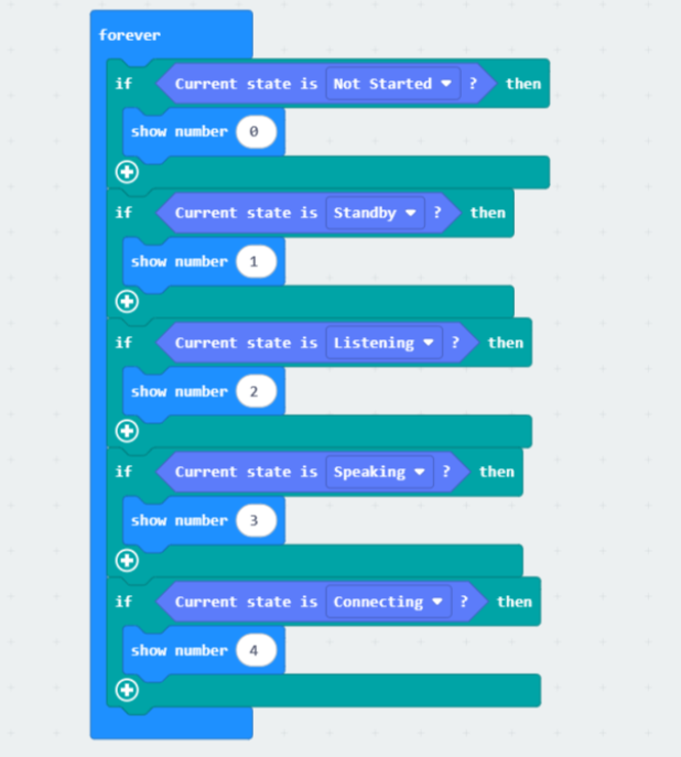
AI conversation
Sample program
Display the K210 module’s status on the micro:bit LED matrix.
Effect demonstration:
WIFI image transmission
A 2.4GHz Wi-Fi network is required. Please refer to section WiFi Stream for network configuration details.
To start image transmission, access the IP address displayed on the module using a web browser on any phone or computer within the same local area network (LAN).
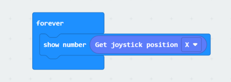
Sample program
Use the micro:bit to display the joystick’s X-axis value from the webpage on the core board’s LED matrix.
Effect demonstration: